ABU Robocon 2020
Pass and Kick Bots for Robo Rugby 7s Fiji Challenge
2020 Contest Theme
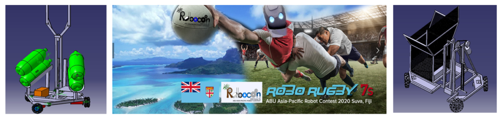
Robo Rugby 7s
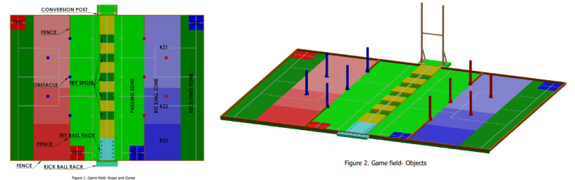
The ABU Robocon 2020 Suva contest is to play rugby 7’s game using two robots and five obstacles as five defending players. The highlight of this game is how the two robots collaborate to score Try and the Goal Kick. The main and unique challenge of this game will be Goal Kick, kicking the Kick Ball over the cross bar of the conversion post because of the unique shape of the rugby ball. The audience will be fascinated if the robot made all the Goals successfully. We are looking forward to witnessing exciting games of unique robots built by the young budding engineers in Suva, Fiji. Based on this concept, ABU Robocon 2020 Suva is designed to promote the idea of “Rugby 7’s”. A game is between Red and Blue teams. It lasts three minutes at most. Each team has two robots known as Pass Robot (PR) and Try Robot (TR). The two robots can be either manual or automatic. The PR starts from the PR Start Zone. The PR picks up one Try Ball from the Ball Rack and passes the Try Ball from the Passing Zone to TR located in the Receiving Zone. The TR starts from the TR Start Zone and moves into the Receiving Zone to receive the Try Ball from PR. The TR then goes along the five defending Obstacles to score the Try in the one of the five Try Spots. After a successful Try by TR, a kick step can be taken from the Kicking Zone to make the Goal. The game continues until all the seven Kick Balls are used or when the 3 minutes passed.

Robots Desgin
MR1: Pass Bot
Overall Dimensions:
- Length – 720 mm
- Game Length – 1000mm
- Width – 620mm
- Game Width – 1000 mm
- Height – 830mm
- Game Height – 1200mm
- Weight – 11kg
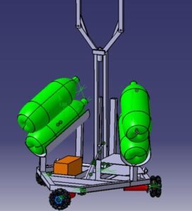
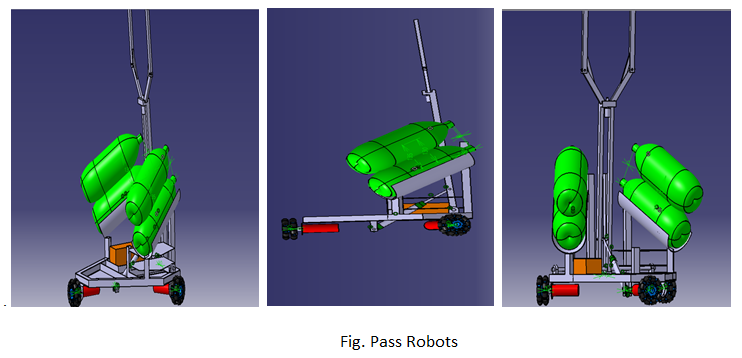
Fig. Pass Robot
Type of Drive: Three Wheel Holonomic Omni-Wheel Drive
The base has been framed by welding Aluminum 6061 hollow box sections. The cross-section used is 0.98’’x0.98’’ and 2mm thick. Aluminum ensured an efficient lightweight frame with uniform weight distribution. Also, as Aluminum has a low density (2.70 g/cm^3) compared to other common metals available in the market, it made the robot lightweight while ensuring swift translation and sturdiness of the base. Thus, a hexagonal-shaped base with internal edges made the robot capable of withstanding the forthcoming mechanisms well. The dimensions have been taken to be 180mm (edge length) of the hexagon for ensuring a compact and an easy to handle system and ensure collision-free movement through compact zones. Also, it is compatible with a Three-Wheel Holonomic Omni-Wheel Drive. The mounting for the three wheels is done in the exact centers of alternate sides of the hexagon.
Three Wheel Drive was preferred because of its rich maneuverability and simple control. In the case of four-wheel drive, the structure of the base experiences stress as the side of the base of which the wheel has left the ground contact is already in stress. This causes instability of the base whereas, in a three-wheel drive, the wheels are always in one plane and will always be in contact with the ground. This provides extra stability to the base.
The motors used were 12V DC Planetary Geared motors having a 438rpm and a stall torque of 23.55kgcm. The heading value was then used for calculating the error in its path. The Hall effect sensor is mounted on the motor which facilitates position sensing, rotary encoding and motor control which ensures smooth and rapid turning.
Actuators and Sensors used:
- Actuators Used:
Sr. No. | Component | Specification | Quantity | Usage |
1 | Planetary Geared Motor | 12V DC, 438rpm, 23.55kgcm stall torque | 3 | Three Wheel Holonomic Omni Wheel Drive |
2 | Air Cylinders | Ø20 bore diameter, 100mm stroke length | 1 | Rugby ball passing mechanism |
3 | DC Geared Motor | 12V DC,3.5kgcm stall torque | 1 | Gripping Mechanism |
● Sensors Used: |
|
| ||
Sr. No. | Component | Specification | Quantity | Usage |
1 | MPU-6050 magnetometer | 3 axis accelerometers, 3 axis gyroscopes | 1 | Three Wheel Holonomic Omni Wheel Drive |
2 | Hall Effect sensor | Current: 4mA(max) Operating voltage:2.3V | 1 | Position sensing, rotary encoding and motor control |
Ball picking and Passing Mechanism:
The link has an extension of two arms (gripper) mutually parallel to the base as well as each other. Further, as the gripper grips the ball, its self-weight will make it fall inclined inwards. The link is pivoted at one end of the base which is actuated by a pneumatic cylinder. It gives the arm an angular displacement which projects the ball towards the try robot.
The steps of passing are shown in Figure. The mechanism implied for picking the rugby ball includes a pivoted arm-like architecture. Two metallic strips of 100mm each behave as the gripper arms. A single air cylinder of 100mm stroke length is being used for imparting angular movement to the metallic strips and has an extended gripper mechanism of 25mm to hold the clamping mechanism near the free end. The clamping mechanism consists of a screw and nut. The mechanism is used the rotary motion of the screw to grip the ball. The screw is powered by a high torque 12V DC Geared motor of 300rpm and 3.5kgcm torque. This screw rotates into a nut where the nut is pivoted to gripper arms. The gripper is used to hold the rugby ball securely. One of the main advantages of this mechanism is that as the rotation of the motor can be controlled the clamping position of the gripper can be controlled, thus making it a fast, efficient, and precise method. Air cylinder-actuated mechanism ensures a stable lifting of the rugby ball and also ensures the precise placement on the throwing platform.
The throwing mechanism is used to throw the rugby ball into the Receiving Zone. It consists of throwing arms of MS metallic strips pivoted at a specified distance with the help of a connecting rod and a bearing joint to a pneumatic air cylinder. The pneumatic air cylinder of 100mm stroke provides the necessary force to throw the ball to the receiving zone. Air Cylinder is being used as it is fast and will provide the necessary impulse to throw the ball in the desired position. To eliminate the problem of pressure variations, a pressure regulator is used throughout the mechanisms to ensure the stability and repeatability of results.
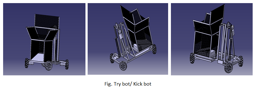
MR 2: Try Bot / Kick Bot
Overall Dimensions:
- Length – 800 mm
- Game Length – 1200mm
- Width – 600mm
- Game Width – 1200 mm
- Height – 1200mm
- Game Height – 1500mm
- Weight – 17kg
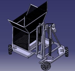
Fig. Try/ Kick Robot
Type of Drive: Four Wheel Holonomic Omni-Wheel Drive
The base has been framed by welding Mild Steel 6061 hollow box sections. The cross-section used is 0.78’’x0.78’’ and 2mm thick. Mild steel ensured an efficient frame with uniform weight distribution. Also, Mild steel has a good shock-absorbing capacity as compared to other common metals available in the market, it made the robot base strong while ensuring swift translation and sturdiness of the base. Thus, a square-shaped base with internal edges made the robot capable of withstanding the forthcoming mechanisms well. The dimensions have been taken to be 125mm (edge length) for ensuring a compact and an easy to handle system and ensure a collision-free movement through compact zones. Also, it is compatible with a Four-Wheel Holonomic Omni-Wheel Drive. Four Wheel Drive was preferred because of its rich maneuverability and simple control. The motors used were 12V DC Planetary Geared motors having a 438rpm and a stall torque of 23.55kgcm. The heading value was then used for calculating the error in its path.
The Hall effect sensor is mounted on the motor which facilitates position sensing, rotary encoding, and motor control which ensures smooth and rapid turning.
Actuators and Sensors used:
- Actuators Used:
|
Sr. No. |
Component |
Specification |
Quantity |
Usage |
|
1 |
Springs |
Outer diameter:18.237 Inner diameter:15.27 Max load:84.516N |
2 Spring loaded kicking mechanism |
|
|
2 |
High torque Worm Geared Motor |
12V DC, 438rpm, 23.55kgcm stall torque. |
4 |
Four Wheel Holonomic Omni Wheel Drive |
- Sensors Used:
|
Sr. No. |
Component |
Specification |
Quantity |
Usage |
|
1 |
Hall Effect sensor |
Current: 4mA(max) Operating voltage:2.3V |
5 |
Position sensing, rotary encoding and motor control |
|
2 |
MPU-6050 magnetometer |
3-axis accelerometer, 3 axis gyroscopes, |
1 |
Three Wheel Holonomic Omni Wheel Drive Position Feedback |
|
3 |
Greybotics line follower sensor |
6 array sensors |
1 |
Line Following |
|
4 |
Limit Switches |
12V DC, Electromechanical |
2 |
Try ball placing mechanism |
Ball receiving mechanism
For the ball receiving mechanism here a square-based basket structure is used where the ball when passed bypassing bot gets precisely landed in the basket, the basket holds a gate from which the ball is allowed to fall in try spot. The opening of gates is made done by limit switches which get actuated by self-weight of the ball.
Try Mechanism
For try mechanism there is slope based wooden structure is provided where it is elevated at an angle of 40 degrees with the base ground. The inclined plane consists of a small door-like structure that is actuated when the limit switch is pressed by the self-weight of a rugby ball. When the ball rolls down the limit switch gets pressed this, in turn, opens the gate to allow the ball to fall in the try spot more precisely without touching the walls of the try ball zone.
Kicking Mechanism
For precise kicking through the conversion post here we made use of 4 spring-loaded kicking legs. Here the kick is located at a height of 50cm where the kick is pivoted at the upper point. The kick bar is actuated by a DC planetary geared motor where it is twisted at an angle till 200 degrees, this twist allows the spring to stretch storing enough energy to kick the ball and when it is released the stored energy is converted to impact force thus in turns kicking the ball through conversion post. Here the precise movement of the kick leg is actuated by a DC planetary geared motor of 23.55kgcm stall torque. After kicking the ball is kicked in projectile motion successfully achieving 1.5m of height and a total horizontal distance of 10m with a precise passing through conversion post.
Tools Used
- Hardware Design: Catia, Solidworks and Fusion 360
- Structural Analysis: Ansys
Acknowledgement
All thanks to Trinity College of Engineering and Research and mentor Prof. Vijay Hole for his incredible guidance. Special thanks to entire ABU Robocon team memebers for all their hard work. Altough the event was cancelled after virtuals for the year 2020 due to Covid. Still we had a great time and team work.
Gallery